

In optical communication networks, optical waveguide devices are essential components. To use these optical waveguide devices, the first thing to solve is the packaging of optical waveguides and fibers or FA. The most critical issue is to solve the low-loss docking between optical waveguides and fibers or FA. This requires sub-micron alignment accuracy, which requires the introduction of specialized alignment equipment packaging to achieve.
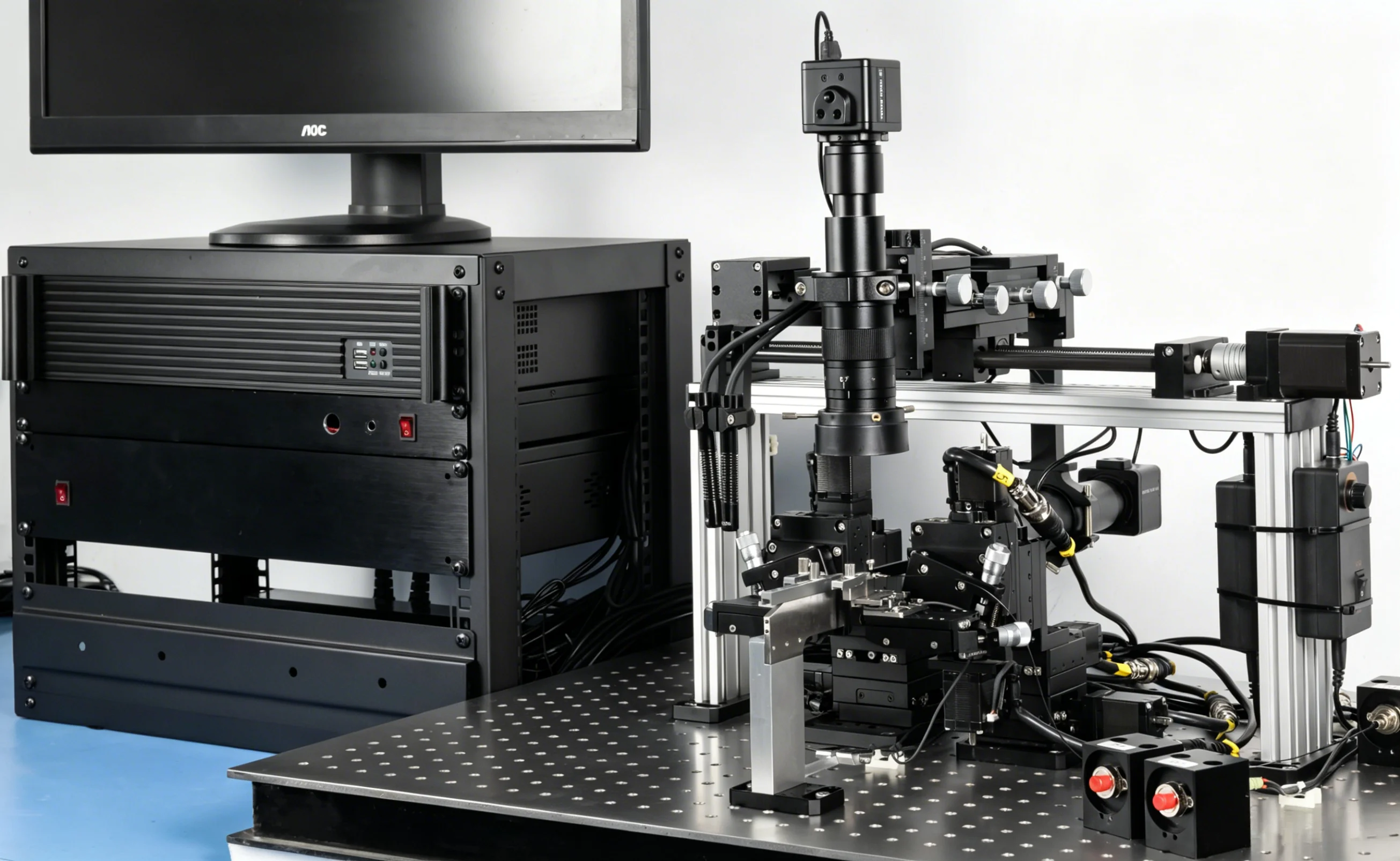
QICEQUIP, using its technological advantages, has developed an optical waveguide alignment packaging and detection system that solves this problem very well, with excellent performance-to-price ratio.
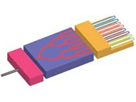
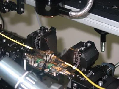
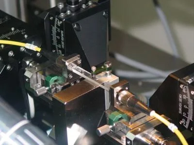
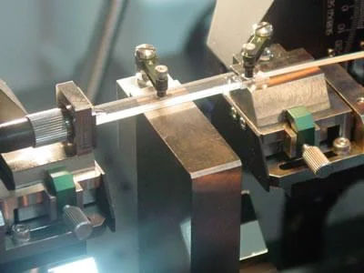
- Sub-micron level adjustment accuracy
- Using alloy materials to manufacture holders, greatly reduces the possibility of power drift.
- Using proprietary contact sensing technology, quantitative adjustments can be made to the parallelism and end clearance of device ends, making alignment more reliable and accurate, significantly reducing the possibility of insertion loss and uneven UV glue.
- Powerful software, can control 2 systems by one computer.
- An easy-to-use upper and rear observation system, facilitating better observation of the device.
- Automatic initial light search, convenient operation, and improved efficiency.
- Automatic dispensing and UV curing.
- Modular design, easy to expand and update, and custom systems can be provided based on customer-specific requirements.
This system can be used for alignment packaging of various passive components, as long as the holders replaced, it can be applied to these devices. For example: AWG, Coupler, Splitter, VOA and so on.
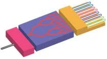
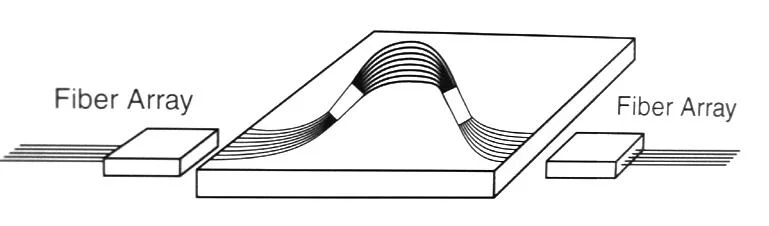
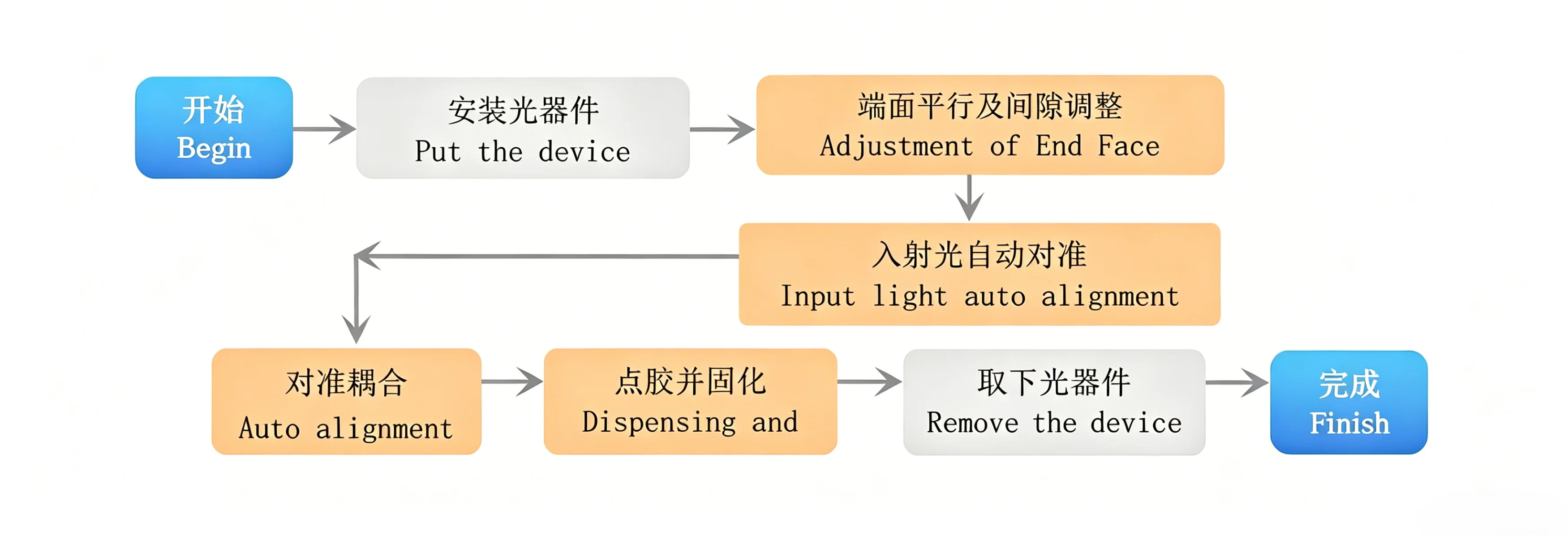
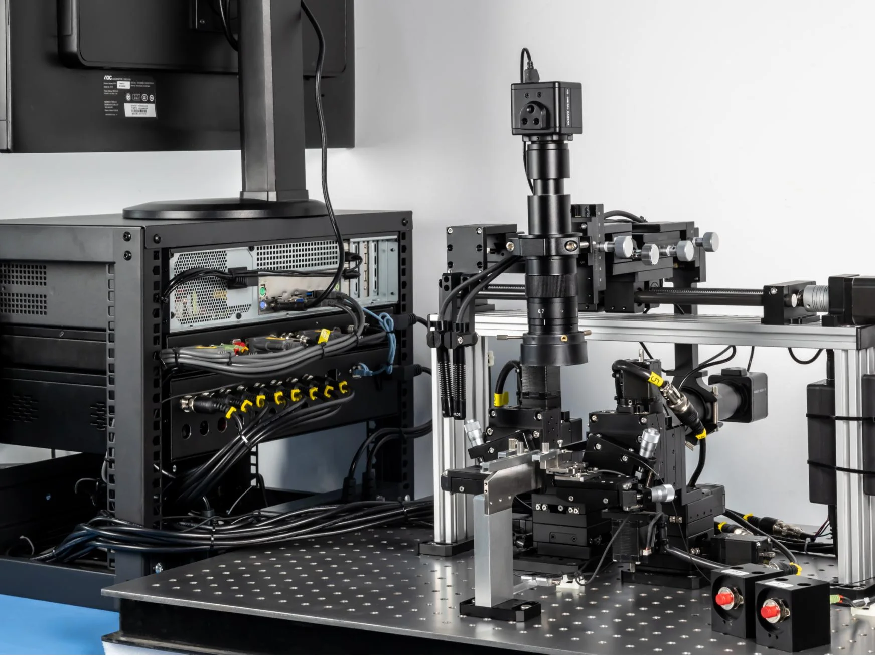
- Alignment Unit
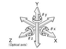
- Input/output motorized 6-axes stages and the controller
- FA Holder
- Upper and back-end observation unit
- Zoom Lens
- CCD camera
- Monitor
- The stages
- Light source
- UV light source
- Light source
- Power meter
- Vibration Isolation Table, Instrument Bracket
- Software
- Computer and the motion control card
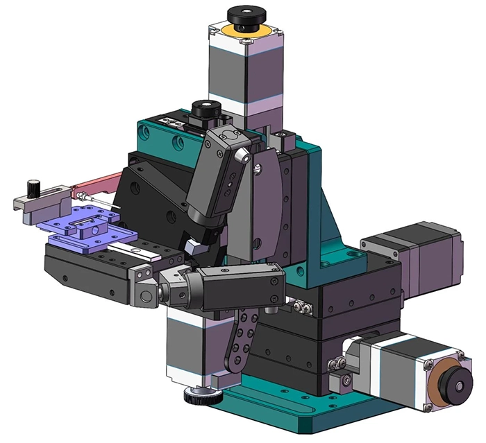
The alignment unit is the core of the entire system and is crucial for precision control. At the input and output ends, two sets of precision six-axis fine-tuning stages are employed, with specifications outlined in the table below.
| Axis | Motorized/Manual | Travel | Resolution | |
|---|---|---|---|---|
| Input/Output Stage | X | Motorized | 20mm | 0.1μm/pulse |
| Y | Motorized | 20mm | ||
| Z | Motorized | 20mm | ||
| θx | Motorized | ±4° | ||
| θy | Motorized | ±4° | 0.0015°/pulse | |
| θz | Motorized | ±8° | ||
| Observation Unit | Z | Motorized | 200mm |
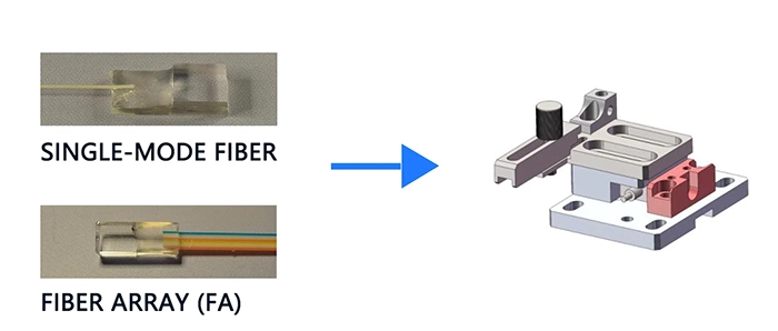
In the alignment system for passive devices, the primary fixtures used are fiber fixtures, waveguide fixtures, and FA fixtures. If standard commercialized components are used for packaging, the fixtures for both fiber and FA are generally the same.
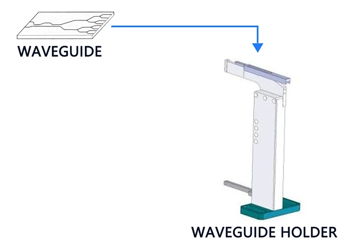
The waveguide holders vary depending on the customer's specific device. Generally, waveguide holders are simpler than fiber holders.
The observation system is primarily designed to observe the conditions of the upper and rear surfaces of the device during alignment. It mainly consists of a microscope zoom lens, CCD camera, monitor, and light source. Additionally, there is a fine-tuning stage for adjusting the two lenses in three directions each.
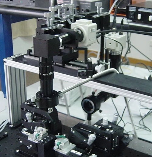
The magnification factor of the lens = The optical magnification factor × TV magnification factor
= 46~291 times(1/3″ CCD, 19″ Monitor)
The work distance of the lens: 9cm, 18cm
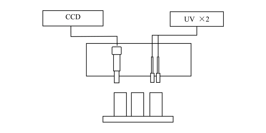
- UV light curing
- The dispensing is auto, and movement along the optical axis is achieved using a fine-tuning stage.
- The system comes with an integrated light source and a three-channel power meter. The light source has wavelengths of 1310nm and 650nm.
- The power meter meets the requirements for alignment, featuring high sensitivity and rapid response.
- The stages can be driven through computer mouse operations.
- Real-time display of optical power meter readings.
- Test results can be saved to an Excel file.
- Manually adjust the gap and parallelism of the end faces.
- Automatic initial light search.
- Automatic Alignment: Capable of XY alignment, XYZ alignment, and XYZ rotation alignment.
- System Configuration: Setting various parameters of the control system.
- Software Interface: Chinese/English
During the system acceptance, we used an 1×8 Coupler. Aligning this device on our system meets its publicly stated technical specifications ≤10.3dB.
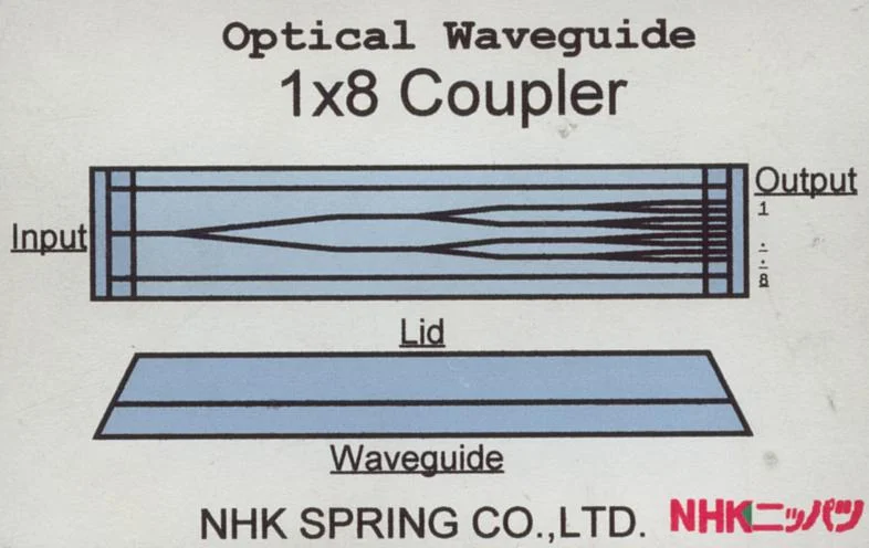
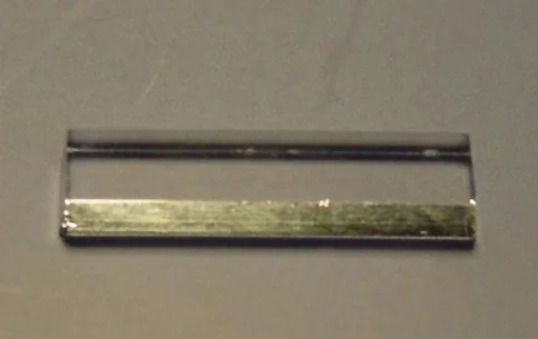
| 1×4 | 1×8 | 1×16 | 1×32 | |
|---|---|---|---|---|
| Insert Loss | ≤7.0dB | ≤10.0dB | ≤13.0dB | ≤17.0dB |
| Uniformity | ≤0.6dB | ≤0.8dB | ≤1.2dB | ≤2.2dB |
| PDL | ≤0.1dB | ≤0.1dB | ≤0.3dB | ≤0.3dB |
| Operating Wavelength | 1260~1360/1480~1580nm | |||
| Operating Temperature | -40~85℃ | |||